Showing posts with label voltage control. Show all posts
Showing posts with label voltage control. Show all posts
April 17, 2013
misc. banks on the 263v
The 263v has been a lot of fun. When I programmed the scales, I had a bunch of left over memory spaces. I filled those spaces with random voltage sequences that are similar to the ones in the middle sections of the 266. Of course they are addressed by control voltage instead of pulses, so they have different uses. I threw in a set of 16 smooth random patterns. If you send in an LFO, you get back something like the fluctuating randoms in a 266, well not "random" but fluctuating. Finally, I through in some pulse sequences and some melodic sequences. Using the random sequences and the melodic sequences is a bit like dropping a sample loop into music (you have to trim the start time and length using a voltage processor). I hope that these functions add something useful to the toolkit.
BTW. I also got it to track 2 volts/octave for the old Buchla guys who need that.
October 15, 2008
This ol' 281

There are two versions of the 281 Quad Function Generator. I have one of each in my system. The older version has blue PCBs and circuitry for remote control. The newer, yellow PCBs and the "remote" switch does nothing more than turn on the LED. I received this older one as part of a trade, in dysfunctional condition. Just one of the 4 envelopes was working. The panel is beat up, some of the silk screen has come off, presumably from stickers being stuck to it for 30 years. The knobs were discolored and the arrows had worn off. One switch was broken and one was missing.

I replaced the switches and all the knobs. Then, I attacked the circuitry. After some song and dance, I found that the CA3080s on all three and the LF356s on two were not working. The odd part is that 4 out of 5 of these were already in sockets (not all the chips were) and all 5 were metal cans. It seems so much less cool to put in plastic DIP chips, but whatever works. Aren't these bad boys supposed to be MORE robust?
This design has resistor values on the schematic for 15volt systems or 10volt systems. i came to find out that mine is set up for 10volt systems, which makes it match my yellow board version. Anyway, it's nice to have it working.

Labels:
281,
envelope,
repair,
volatge range,
voltage control
October 5, 2008
107 voltage Controlled Mixer
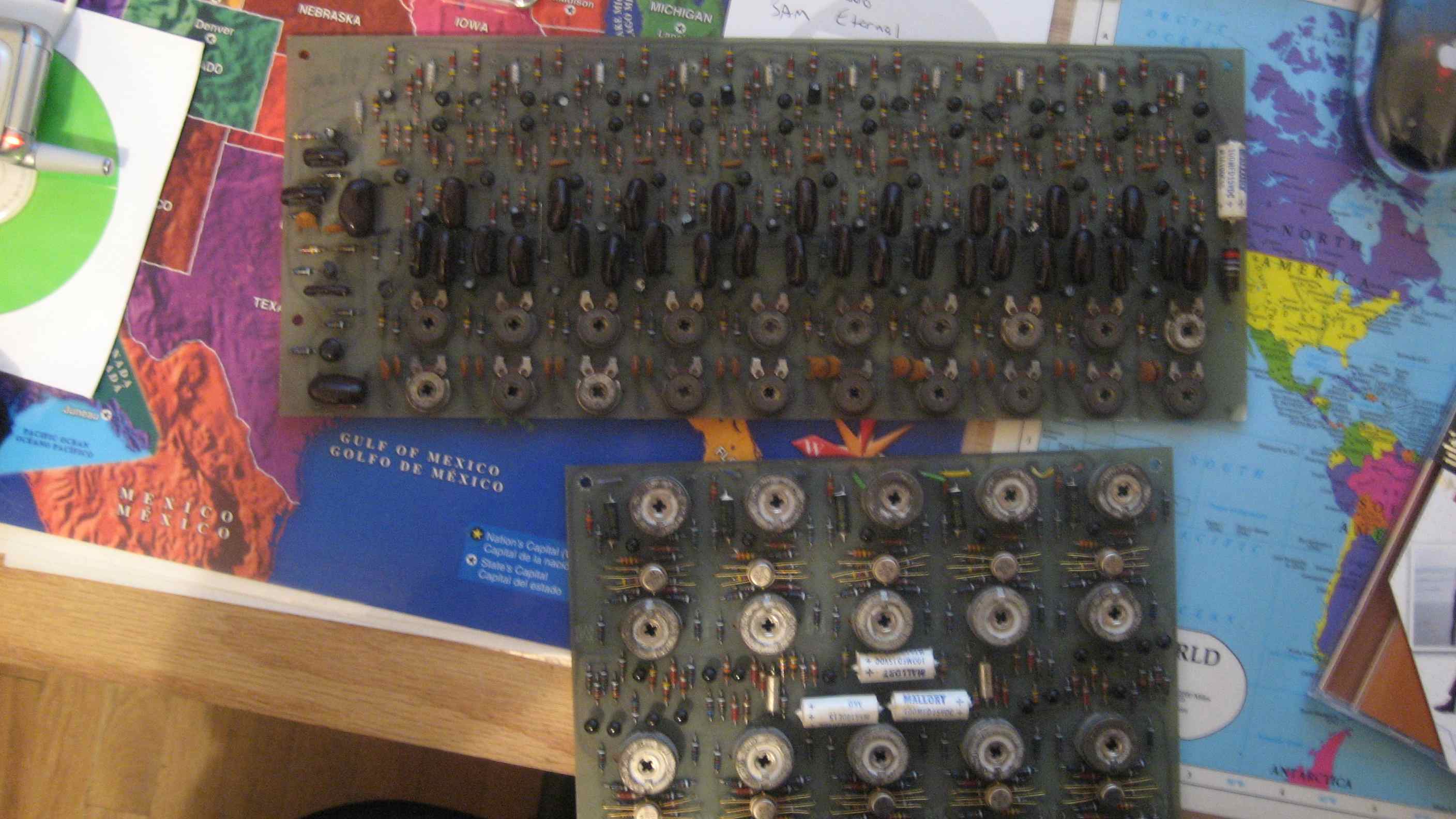
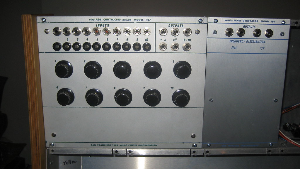
In a lot that I bought, I ended up with a PCB from a 107 Voltage Controlled Mixer and a 114 Touchplate Keyboard, shown below. I also have a 160 Noise Source panel that I haven't done anything with yet, but that's not important to this post. I ended up selling the 114 on ebay because I could not imagine making a panel and touchplates that would be convincing and anyway I don't really care for that module. However, I was fortunate enough to find a Buchla owner who had a 107 panel in their system, backwards, as a blank space filler. So I had both the panel and the PCB, I needed only to get the pots and jacks and wire it up.


Assembling this module was an easy enough task. Since the schematic is on the list of ones I WISH I had, I found myself asking around if anyone had this module and would take a picture of the inside and tracing out the PCB to make up my own schematic. Soon enough, I realized that the pots on the panel don't control the VCAs on each channel! They are actually input volume controls.That means that you can't open up a channel without sending external voltage. Totally weird. I guess that's par for the course with Buchla 100 modules.
After some reverse engineering of my PCB and a picture that I got of someone else's 107 guts, I came to realize this module is the equivalent of ten 110 gate modules tied to two output channels and those 2 then mixed. The nice thing about having a 110 VCA in a 200 system is that it has a much snappier attack than a 292 and allows you to cheat nature a little and make sharp percussive sounds. A 107 let's you do a whole drumkit like that!
As it turns out, the PCB was totally functional as soon as I wired it up. This system is coming together slowly but surely.

Labels:
100,
107,
buchla,
vca,
voltage control
Subscribe to:
Posts (Atom)


