October 18, 2008

LEDs for Lamps

I dug into the 280 quad envelope generator's indicators. Originally, Buchla used lamps for the indicators on his modules. This evolved into the use of LEDs in later and current modules. Don couldn't decide how to mount LEDs either, some modules had them mounted to a "motherboard" PCB, some had them mounted to terminal strips bolted on the panel. The owner of this 280 decided to have me replace the lamps with LEDs, so they would be faster as well as last longer. I decided to change all four, even though only two were blown.

The offending lamps are sealed into a panel mounted enclosure that was intended to be disposable. Sadly, 40 years have passed since they were installed and they are no longer being manufactured. The only solution that will keep the aesthetic of the panel is to cut off the back of the enclosure and put a new light inside it. This is the cute lamp that was inside.


Luckily, a 5mm LED fits inside perfectly. I have chosen to use RED diffused type. They light up nicely with no extra resistor! Here is the job partially finished. The sawed off lamp on the left and an unaltered one on the right.


And here all done.


I forgot to snap a picture of the LEDs lighting up, but they look great. Now the fast, "blip" type envelopes can be seen, which was not the case with the original lamps.

October 16, 2008

Garage Sale 259


Today's project was a broken 259. The modulation oscillator was not putting out anything in the sawtooth position of the switch. The Harmonics Order control was doing nothing, but voltage was effecting it. Judging simply from the outside of this module, I can assume it was not built at the Buchla factory, but was a kit purchased at the garage sale a few years ago. The blue LEDs (yuck!) and the black big knobs were the first tip off.

Once I had this guy open, I was treated to confusing extra wires, which I came to see were there to get around using the remote switch as intended and to use it to engage some extra trim pots. I guess that the switch puts the trimmed CV ins into 1.2v/oct mode to work with a 200e system. Why the builder didn't just add some fixed resistors and make the CV ins ALWAYS 1.2v/oct is beyond me.

The Harmonics Order control problem was just some bad soldering. During assembly the iron was held on one of the pot's pads for too long and it lifted off the board. Finally, the pad tore away from the trace.


The modulation oscillator turned out to be putting out a sawtooth wave, but it wasn't getting to the output. The LF13331 is the switching chip that I always HOPE isn't blown, since it is hard to come by. In this case, the working saw wave told me that the chip was fine. It turned out to be a faulty 4555 decoder. I think if the LF13331 had been the problem, the LED on the panel would have been showing the saw mode, but it wasn't.


Upon re-assembly I tried everything out and came to notice that the lower order harmonics were coming out as just a sin wave. When I tweaked the trimmer I got a little action, but only about 25% of the total that is normal for the wave folder section. It turns out, the 2N3958 dual FET transistor that is supposed to be there was substituted with 2 2N4339 FETs. These FETs don't have as much gain I guess, because they weren't doing the job. Rather than tweak resistor values, I put in the real thing and it worked perfectly!


Now it's working properly. I even added some rubber caps to the switches(not in the picture). I don't mind the black knobs, in fact I prefer them to the unskirted ones I got, but I HATE the blue LEDs.

October 15, 2008

This ol' 281


There are two versions of the 281 Quad Function Generator. I have one of each in my system. The older version has blue PCBs and circuitry for remote control. The newer, yellow PCBs and the "remote" switch does nothing more than turn on the LED. I received this older one as part of a trade, in dysfunctional condition. Just one of the 4 envelopes was working. The panel is beat up, some of the silk screen has come off, presumably from stickers being stuck to it for 30 years. The knobs were discolored and the arrows had worn off. One switch was broken and one was missing.


I replaced the switches and all the knobs. Then, I attacked the circuitry. After some song and dance, I found that the CA3080s on all three and the LF356s on two were not working. The odd part is that 4 out of 5 of these were already in sockets (not all the chips were) and all 5 were metal cans. It seems so much less cool to put in plastic DIP chips, but whatever works. Aren't these bad boys supposed to be MORE robust?

This design has resistor values on the schematic for 15volt systems or 10volt systems. i came to find out that mine is set up for 10volt systems, which makes it match my yellow board version. Anyway, it's nice to have it working.

October 14, 2008

Early To Rise


A while back, in the Buchla Yahoo Group, I got involved in a discussion about why some 200e modules will not advance a 245/246 Sequencer and subsequently my 243 Programmable Pulser module. I suggested that it was the slow rise time of the 249e, and likely every other 200e module, that caused the problem. Ezra wrote that he thinks it's the voltage level of the pulses, since they only peak at 10 volts, not 15 volts like the old black knobbed modules from the 246 era. Well, I am not one to let sleeping dogs lie, so Reed and I did a little research on as many modules as we had available and my scope. This is what we found.

  • 249e - 8.5 volt peak - 300µS rise time - does not step the 246
  • 281 - 15 volt peak - 10µS rise time - steps 246
  • 230 - 15 volt peak - 5µS rise time - steps 246
  • 257 pulse from 281 sent through - 10 volt peak - 80µS rise time - steps 246
  • 248 all pulses out - 14.75 volt peak (no spike, just gate) - 500nS rise - steps 246
  • 248 CV out alternating between high and low - 200µS rise - steps 246
  • 225e modded for bigger pulses - 12.75 volt peak - 150µS rise time - steps 246
  • 259 square wave out of mod oscillator - 10 volt peak - 5µS rise time - steps 246
  • 259 saw wave (falling even though the panel shows rising) - 10 volt peak - 5µS rise time - steps 246

The 246 schematic specifies that it's "input sens." is 3V, 100µS rise. The 284 schematic specifies it's "nominal input sensitivity: 5V (5 pulse, 3V sustain)" and "required rise time (15v):3ms.). Interestingly, the 284 would trigger from the 249e. Where does that leave us? Why does the 225e modded to have a higher gain on the output opamps work if it's not about gain? Why is 10 volt enough coming from the 257, but not the 249e? Why is 10 volts not enough if the "sens" of a 246 is 3v? These are all very good questions. I have a guess.

The issue is not wither the rise time or the voltage level, it's both. Specifically, The rise time to the threshold. In the 246's case, the rise time from 0 to 15v needs to be 100µS. On the scope, the rising voltage slope is not linear. It appears to be an RC curve, rising quickly at first and slowing as it approaches the asymptote. So the "rise time" is not actually the issue, but the speed of the rise. If the pulse's total voltage is 15v (WAY above the threshold), it will be moving much faster as it passes 3v than if it is only rising to 8.5v.

My assumption is that the output of the microprocessor in the 249e is PWM that is filtered to make continuous voltages and there's no way to raise the cutoff frequency of that filter to speed up that rise time.

The gain on the pulse outputs could be pumped up, like I did to that 225e, or an opamp comparator could be added between the pulse input jack and the circuit of the sequencer/pulser. A 281 could be triggered with very short time constants and it's big daddy pulse output used to step the sequencer. A banana to 1/8" lead could be used to send the sluggish pulse into a 230 to sharpen it up. I'm considering changing the input section of the Pulser to be more understanding.

I'll close with a quote from the 242 clock schematic. I have not tested any 100 series modules for rise time, but they seem to be way faster than anything 200e...

"pulse width: ~50µS
risetime: ~3µS
[<10µS required to operate models 123, 146 sequencers. when these are phased out, we may increase to ~20µS]"

My first 280


Today I worked on my first 280 Quad Envelope Generator. I was told that the top envelope seemed to get confused when it got pulses from certain modules. Once it got into this confused state, it was inconsolable. I didn't understand this condition at all. 2 of the 4 lamps are burned out as well.

There are 2 versions of the 280 module. I'm not sure what the deal is, since they were designed only 3 months apart, on March 23rd and June 21st of 1971. I guess this means the first one was a dud of some kind, and I don't know how many, if any are out there. This one was of the second type. (I'm guessing there was a third design as well, since the pictures I got from www.electricmusicbox.com show one with no lamps or pulse outputs and both schematics I have show these.)


Anyway, the problem turned out to be that someone had replaced the input comparator opamp with an LM307 instead of a uA741! I never would have guessed that this would be a problem, but when I opened it and saw that only the weird channel had a different opamp, obviously I was suspicious.

The lamps are still dead. Since they are enclosed in a lens apparatus that is panel mounted, they are not an easy replacement job. I have been told that cutting the back off and sticking another lamp inside the lens is the only way to keep the look. The owner and I have decided to replace all 4 with LEDs inside the lens, since the lamps are so slow they don't even light on short envelopes. Plus, I really don't want to replace them again.

Oddly, the 292 on the bench today had a bad uA741 as well. They must suck. ;)

Overall, I have developed a fondness for this module. On the surface, it would seem that a 281 is better than a 280 or 284, and capable of all of their tricks plus more. But, this little guy does his job with a swagger that can't be duplicated. Oh, and the output swings a FULL 0-15 volts.

October 7, 2008

The Good Thing About Standards: So Many To Choose From

I love Buchla as much as the next guy (probably more), but his evolution can teach a designer a thing or two. On the subject of standards we can definitely learn to commit.

The 100 series has a few conventions. The power supply used +24 volts, +15 volts and a single Ground. The audio level are at 0 dBV or roughly 1 volt RMS. The CVs swing from 0 to +15 volts. All pulses are on RED banana jacks and all CVs are on BLACK banana jacks. Pulses are 15 volts. All indicators are large 24 volt lamps. Most modules in the system were a single PCB so depths weren't too big, some had two PCBs, but that doesn't matter because the cabinets stand upright and have an open back. Modules are labelled "San Francisco Tape Music Center" or "CBS Musical Intruments."

The early '70s modules of the 200 series or so called "black knob" modules had their own set of slightly modified standards. The power supplies had +/-24 volts, +/-15 volts, +/-5 volts and two Ground lines. Audio levels are +4 dBu professional line level (1.228 V RMS). CVs swing from 0-15 volts. All pulses are on RED banana jacks and all CVs are on BLACK banana jacks. Pulses have a short 15 volt spike followed by a 7.5 volt sustaining gate. Indicators are 24 volt lamps, or small LEDs. Panel components are all mounted to the panel and wired to the PCBs, which in some cases are as many as 3 deep behind the panel wiring, but parallel to the panel. Each module came in it's own chassis with a Cinch connector hanging out. These boxes were assembled into cabinets and secured down with a bar accross the front. Not that it matters because the cabinet covers up whatever is outside the lines at the top and bottom of the modules, but many modules had no brand name on them at all!

The later 200 series or "blue knob" modules also had a unique set of standards. The power supplies now had +/-15 volts, +5 volts, +12 volts and 2 ground lines. Audio levels remain +4 dBu line level. CVs now swing from 0-10 volts. Pulse outputs are RED banana jacks, but pulse inputs are Orange (sometimes at this stage and always by the end of the 70s). CV ins are still BLACK bananas, but CV outs are now BLUE or sometimes PURPLE bananas. Pulses have a short 10 volt spike followed by a 5 volt sustaining gate. All indicators are red LEDs. Behind the scenes now all controls are mounted on a "mother board" and multipin connectors run to the other PCBs, making assembly easier. Cabinets now have large "boats" where a whole horizontal row of modules shares one chassis, which is a part of the cabinet. Power is still the Cinch connectors, but evolves to 10 pin edge connectors by the end of the 70s. Modules now mount into the cabinet using screws through the panel into the boat using tinnerman nuts. The boats are only 3" deep without the power system, so consideration must be made for if a module can even fit into a cabinet. Some modules (208, 227, 296) have daughter cards mounted perpendicular to the motherboard and can only fit in a boat with no power connector and in the middle where the bottom doesn't slope. The modules are now labelled "Buchla & Associates."

The 200e has it's own unique set of standards. The power supply is a 12 volt DC wallwart that connects to 3 DC-DC converters inside the center boat. These converters put out +/-15 volts and +5 volts, the unregulated +12 volts is available from the wallwart. Audio levels are back to 0 dBV. CVs are 0-10 volts. All pulse inputs are Orange, all pulse outputs are RED, CV ins are BLACK or GREY, CV outs are BLUE, PURPLE or GREEN. Pulses have a short 10 volt spike followed by a 5 volt sustaining gate. Knobs are blue capped if their position will be stored memory or white capped if they won't. Indicators are all different colors of 3mm LEDs. Power is all 10 pin edge connectors (but now with data lines on some pins). All panel components are board mounted, but now most modules are just a single board with the panel components and the whole circuit on it. Being micro based makes them lower parts count in many cases and surface mount stuff is small. Boats in the cainets are even shallower, not allowing some modules to fit. All modules labelled "Buchla & Associates."


What's the point? The point is that on a basic level all Buchla modules can be used together in one system, but these little things make headaches. Later 281 modules don't open up a black knobbed 292 all the way. 208 modules physically don't fit in a 200e cabinet. 249e pulse outputs won't step a 246. Should older modules be updated? Should 200e modules have their outputs boosted? I don't know. How do you put a 284 into a 203 cabinet that has no 24 volt supplies? Good question. I made a daughtercard that boosts a 12 volt rail to +/-24. Or you could just tap a line off of the big cap in the 15 volt supply. It's probably only about 18 volts, but it will work. I have seen a 246 modded with LEDs instead of lamps and with it's oscillator adjusted to not need a 24 volt line. That works, of course that same one had blue knobs on it but that's another story.... Hey at least the panel size has stayed the same.

October 5, 2008

107 voltage Controlled Mixer

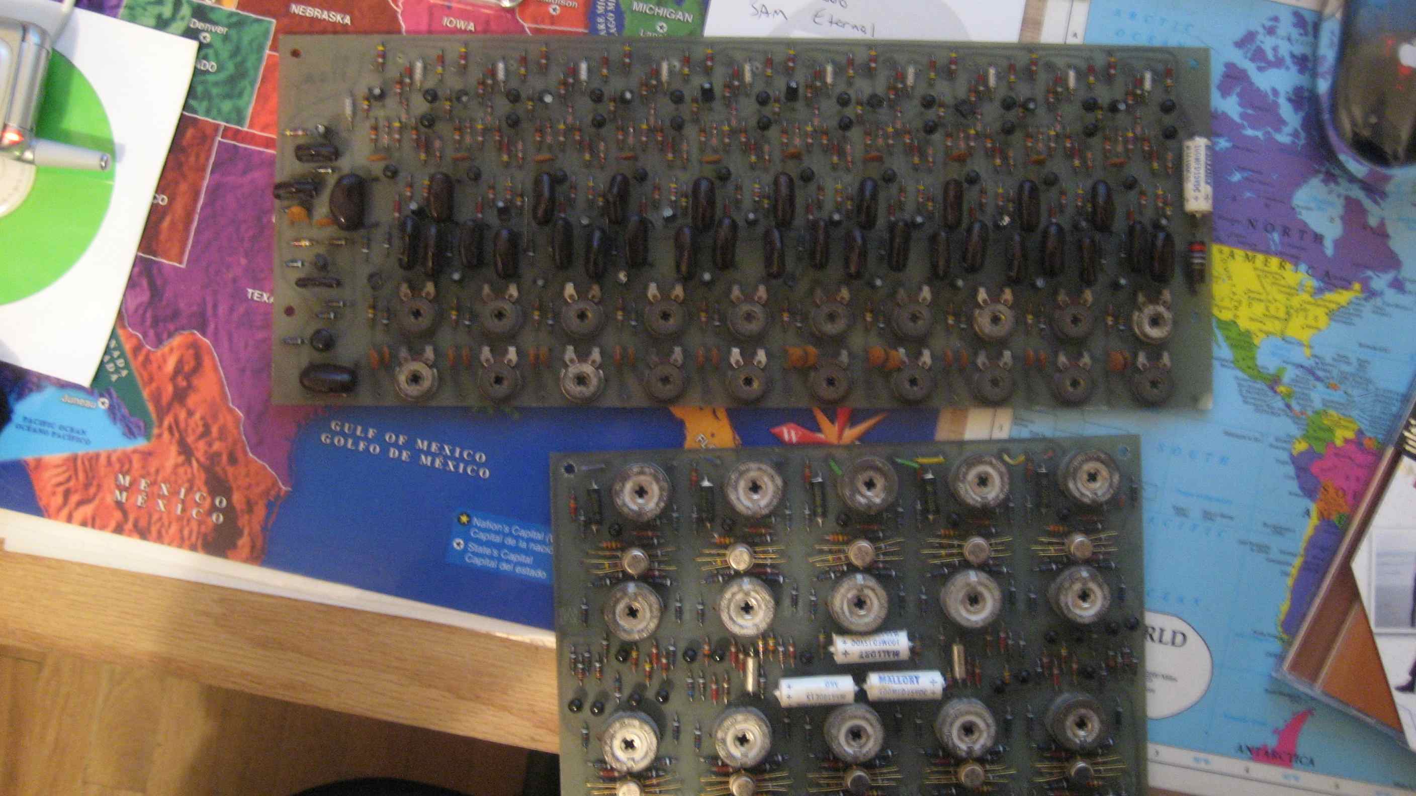
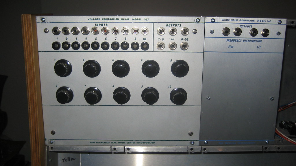
In a lot that I bought, I ended up with a PCB from a 107 Voltage Controlled Mixer and a 114 Touchplate Keyboard, shown below. I also have a 160 Noise Source panel that I haven't done anything with yet, but that's not important to this post. I ended up selling the 114 on ebay because I could not imagine making a panel and touchplates that would be convincing and anyway I don't really care for that module. However, I was fortunate enough to find a Buchla owner who had a 107 panel in their system, backwards, as a blank space filler. So I had both the panel and the PCB, I needed only to get the pots and jacks and wire it up.


Assembling this module was an easy enough task. Since the schematic is on the list of ones I WISH I had, I found myself asking around if anyone had this module and would take a picture of the inside and tracing out the PCB to make up my own schematic. Soon enough, I realized that the pots on the panel don't control the VCAs on each channel! They are actually input volume controls.That means that you can't open up a channel without sending external voltage. Totally weird. I guess that's par for the course with Buchla 100 modules.

After some reverse engineering of my PCB and a picture that I got of someone else's 107 guts, I came to realize this module is the equivalent of ten 110 gate modules tied to two output channels and those 2 then mixed. The nice thing about having a 110 VCA in a 200 system is that it has a much snappier attack than a 292 and allows you to cheat nature a little and make sharp percussive sounds. A 107 let's you do a whole drumkit like that!

As it turns out, the PCB was totally functional as soon as I wired it up. This system is coming together slowly but surely.