Showing posts with label buchla. Show all posts

July 24, 2014

Made From the Best Stuff On Earth

 Don Buchla split up with CBS as a distributor of his products after the 100 Series and in 1970 released the 200 Series Electric Music Box. What is really mind blowing about these first, black knobbed modules is the serious quality of their build. The lighted push buttons on the 246 sequencer have an incandescent lamp in them and are about $75 if you find them now. The pots are military grade CTS panel mounted beauties. C&K toggle switches, Switchcraft audio jacks and Johnson banana jacks were used in all of the original Buchla stuff, so it's easy to overlook them. The LEDs on a 246 sequencer are from the first batch of LEDs to EVER HIT THE MARKET. They are a gold can with a glass dome. If you want to replace these LEDs, you're looking at about $20 EACH!!

Each module came in its own chassis box with a Cinch-Jones pigtail. They were meticulously hand wired. The cabinet holds them down from the front, covering the module and manufacturer's name. They have a significant weight to them. It's crazy stuff and a far cry from the plastic junk that gets churned out these days. Long live the original! (24 volt power rails and all!)


October 18, 2008

LEDs for Lamps

I dug into the 280 quad envelope generator's indicators. Originally, Buchla used lamps for the indicators on his modules. This evolved into the use of LEDs in later and current modules. Don couldn't decide how to mount LEDs either, some modules had them mounted to a "motherboard" PCB, some had them mounted to terminal strips bolted on the panel. The owner of this 280 decided to have me replace the lamps with LEDs, so they would be faster as well as last longer. I decided to change all four, even though only two were blown.

The offending lamps are sealed into a panel mounted enclosure that was intended to be disposable. Sadly, 40 years have passed since they were installed and they are no longer being manufactured. The only solution that will keep the aesthetic of the panel is to cut off the back of the enclosure and put a new light inside it. This is the cute lamp that was inside.


Luckily, a 5mm LED fits inside perfectly. I have chosen to use RED diffused type. They light up nicely with no extra resistor! Here is the job partially finished. The sawed off lamp on the left and an unaltered one on the right.


And here all done.


I forgot to snap a picture of the LEDs lighting up, but they look great. Now the fast, "blip" type envelopes can be seen, which was not the case with the original lamps.

October 16, 2008

Garage Sale 259


Today's project was a broken 259. The modulation oscillator was not putting out anything in the sawtooth position of the switch. The Harmonics Order control was doing nothing, but voltage was effecting it. Judging simply from the outside of this module, I can assume it was not built at the Buchla factory, but was a kit purchased at the garage sale a few years ago. The blue LEDs (yuck!) and the black big knobs were the first tip off.

Once I had this guy open, I was treated to confusing extra wires, which I came to see were there to get around using the remote switch as intended and to use it to engage some extra trim pots. I guess that the switch puts the trimmed CV ins into 1.2v/oct mode to work with a 200e system. Why the builder didn't just add some fixed resistors and make the CV ins ALWAYS 1.2v/oct is beyond me.

The Harmonics Order control problem was just some bad soldering. During assembly the iron was held on one of the pot's pads for too long and it lifted off the board. Finally, the pad tore away from the trace.


The modulation oscillator turned out to be putting out a sawtooth wave, but it wasn't getting to the output. The LF13331 is the switching chip that I always HOPE isn't blown, since it is hard to come by. In this case, the working saw wave told me that the chip was fine. It turned out to be a faulty 4555 decoder. I think if the LF13331 had been the problem, the LED on the panel would have been showing the saw mode, but it wasn't.


Upon re-assembly I tried everything out and came to notice that the lower order harmonics were coming out as just a sin wave. When I tweaked the trimmer I got a little action, but only about 25% of the total that is normal for the wave folder section. It turns out, the 2N3958 dual FET transistor that is supposed to be there was substituted with 2 2N4339 FETs. These FETs don't have as much gain I guess, because they weren't doing the job. Rather than tweak resistor values, I put in the real thing and it worked perfectly!


Now it's working properly. I even added some rubber caps to the switches(not in the picture). I don't mind the black knobs, in fact I prefer them to the unskirted ones I got, but I HATE the blue LEDs.

October 14, 2008

My first 280


Today I worked on my first 280 Quad Envelope Generator. I was told that the top envelope seemed to get confused when it got pulses from certain modules. Once it got into this confused state, it was inconsolable. I didn't understand this condition at all. 2 of the 4 lamps are burned out as well.

There are 2 versions of the 280 module. I'm not sure what the deal is, since they were designed only 3 months apart, on March 23rd and June 21st of 1971. I guess this means the first one was a dud of some kind, and I don't know how many, if any are out there. This one was of the second type. (I'm guessing there was a third design as well, since the pictures I got from www.electricmusicbox.com show one with no lamps or pulse outputs and both schematics I have show these.)


Anyway, the problem turned out to be that someone had replaced the input comparator opamp with an LM307 instead of a uA741! I never would have guessed that this would be a problem, but when I opened it and saw that only the weird channel had a different opamp, obviously I was suspicious.

The lamps are still dead. Since they are enclosed in a lens apparatus that is panel mounted, they are not an easy replacement job. I have been told that cutting the back off and sticking another lamp inside the lens is the only way to keep the look. The owner and I have decided to replace all 4 with LEDs inside the lens, since the lamps are so slow they don't even light on short envelopes. Plus, I really don't want to replace them again.

Oddly, the 292 on the bench today had a bad uA741 as well. They must suck. ;)

Overall, I have developed a fondness for this module. On the surface, it would seem that a 281 is better than a 280 or 284, and capable of all of their tricks plus more. But, this little guy does his job with a swagger that can't be duplicated. Oh, and the output swings a FULL 0-15 volts.

October 7, 2008

The Good Thing About Standards: So Many To Choose From

I love Buchla as much as the next guy (probably more), but his evolution can teach a designer a thing or two. On the subject of standards we can definitely learn to commit.

The 100 series has a few conventions. The power supply used +24 volts, +15 volts and a single Ground. The audio level are at 0 dBV or roughly 1 volt RMS. The CVs swing from 0 to +15 volts. All pulses are on RED banana jacks and all CVs are on BLACK banana jacks. Pulses are 15 volts. All indicators are large 24 volt lamps. Most modules in the system were a single PCB so depths weren't too big, some had two PCBs, but that doesn't matter because the cabinets stand upright and have an open back. Modules are labelled "San Francisco Tape Music Center" or "CBS Musical Intruments."

The early '70s modules of the 200 series or so called "black knob" modules had their own set of slightly modified standards. The power supplies had +/-24 volts, +/-15 volts, +/-5 volts and two Ground lines. Audio levels are +4 dBu professional line level (1.228 V RMS). CVs swing from 0-15 volts. All pulses are on RED banana jacks and all CVs are on BLACK banana jacks. Pulses have a short 15 volt spike followed by a 7.5 volt sustaining gate. Indicators are 24 volt lamps, or small LEDs. Panel components are all mounted to the panel and wired to the PCBs, which in some cases are as many as 3 deep behind the panel wiring, but parallel to the panel. Each module came in it's own chassis with a Cinch connector hanging out. These boxes were assembled into cabinets and secured down with a bar accross the front. Not that it matters because the cabinet covers up whatever is outside the lines at the top and bottom of the modules, but many modules had no brand name on them at all!

The later 200 series or "blue knob" modules also had a unique set of standards. The power supplies now had +/-15 volts, +5 volts, +12 volts and 2 ground lines. Audio levels remain +4 dBu line level. CVs now swing from 0-10 volts. Pulse outputs are RED banana jacks, but pulse inputs are Orange (sometimes at this stage and always by the end of the 70s). CV ins are still BLACK bananas, but CV outs are now BLUE or sometimes PURPLE bananas. Pulses have a short 10 volt spike followed by a 5 volt sustaining gate. All indicators are red LEDs. Behind the scenes now all controls are mounted on a "mother board" and multipin connectors run to the other PCBs, making assembly easier. Cabinets now have large "boats" where a whole horizontal row of modules shares one chassis, which is a part of the cabinet. Power is still the Cinch connectors, but evolves to 10 pin edge connectors by the end of the 70s. Modules now mount into the cabinet using screws through the panel into the boat using tinnerman nuts. The boats are only 3" deep without the power system, so consideration must be made for if a module can even fit into a cabinet. Some modules (208, 227, 296) have daughter cards mounted perpendicular to the motherboard and can only fit in a boat with no power connector and in the middle where the bottom doesn't slope. The modules are now labelled "Buchla & Associates."

The 200e has it's own unique set of standards. The power supply is a 12 volt DC wallwart that connects to 3 DC-DC converters inside the center boat. These converters put out +/-15 volts and +5 volts, the unregulated +12 volts is available from the wallwart. Audio levels are back to 0 dBV. CVs are 0-10 volts. All pulse inputs are Orange, all pulse outputs are RED, CV ins are BLACK or GREY, CV outs are BLUE, PURPLE or GREEN. Pulses have a short 10 volt spike followed by a 5 volt sustaining gate. Knobs are blue capped if their position will be stored memory or white capped if they won't. Indicators are all different colors of 3mm LEDs. Power is all 10 pin edge connectors (but now with data lines on some pins). All panel components are board mounted, but now most modules are just a single board with the panel components and the whole circuit on it. Being micro based makes them lower parts count in many cases and surface mount stuff is small. Boats in the cainets are even shallower, not allowing some modules to fit. All modules labelled "Buchla & Associates."


What's the point? The point is that on a basic level all Buchla modules can be used together in one system, but these little things make headaches. Later 281 modules don't open up a black knobbed 292 all the way. 208 modules physically don't fit in a 200e cabinet. 249e pulse outputs won't step a 246. Should older modules be updated? Should 200e modules have their outputs boosted? I don't know. How do you put a 284 into a 203 cabinet that has no 24 volt supplies? Good question. I made a daughtercard that boosts a 12 volt rail to +/-24. Or you could just tap a line off of the big cap in the 15 volt supply. It's probably only about 18 volts, but it will work. I have seen a 246 modded with LEDs instead of lamps and with it's oscillator adjusted to not need a 24 volt line. That works, of course that same one had blue knobs on it but that's another story.... Hey at least the panel size has stayed the same.

October 5, 2008

107 voltage Controlled Mixer

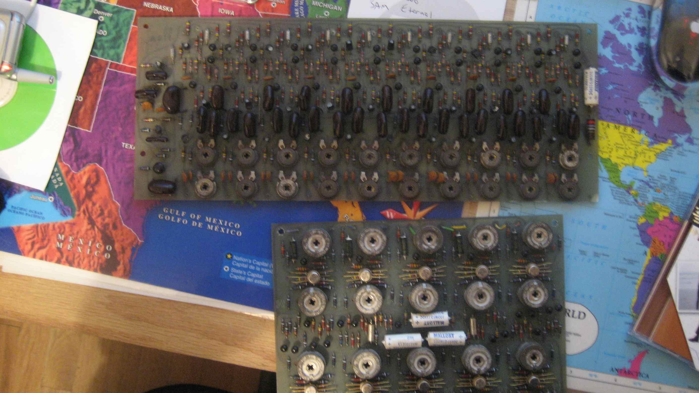
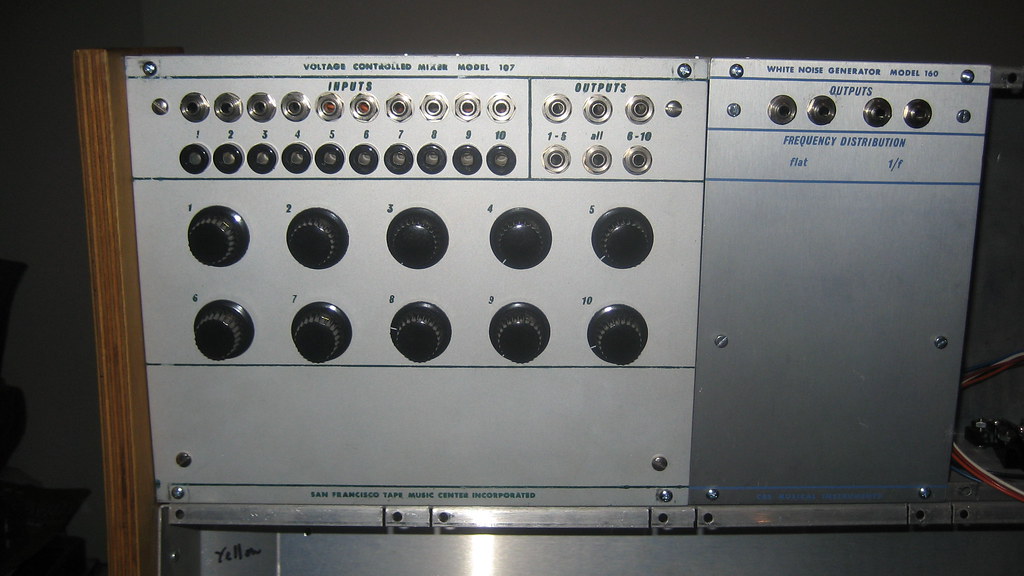
In a lot that I bought, I ended up with a PCB from a 107 Voltage Controlled Mixer and a 114 Touchplate Keyboard, shown below. I also have a 160 Noise Source panel that I haven't done anything with yet, but that's not important to this post. I ended up selling the 114 on ebay because I could not imagine making a panel and touchplates that would be convincing and anyway I don't really care for that module. However, I was fortunate enough to find a Buchla owner who had a 107 panel in their system, backwards, as a blank space filler. So I had both the panel and the PCB, I needed only to get the pots and jacks and wire it up.


Assembling this module was an easy enough task. Since the schematic is on the list of ones I WISH I had, I found myself asking around if anyone had this module and would take a picture of the inside and tracing out the PCB to make up my own schematic. Soon enough, I realized that the pots on the panel don't control the VCAs on each channel! They are actually input volume controls.That means that you can't open up a channel without sending external voltage. Totally weird. I guess that's par for the course with Buchla 100 modules.

After some reverse engineering of my PCB and a picture that I got of someone else's 107 guts, I came to realize this module is the equivalent of ten 110 gate modules tied to two output channels and those 2 then mixed. The nice thing about having a 110 VCA in a 200 system is that it has a much snappier attack than a 292 and allows you to cheat nature a little and make sharp percussive sounds. A 107 let's you do a whole drumkit like that!

As it turns out, the PCB was totally functional as soon as I wired it up. This system is coming together slowly but surely.

October 4, 2008

That 214 Booster Board

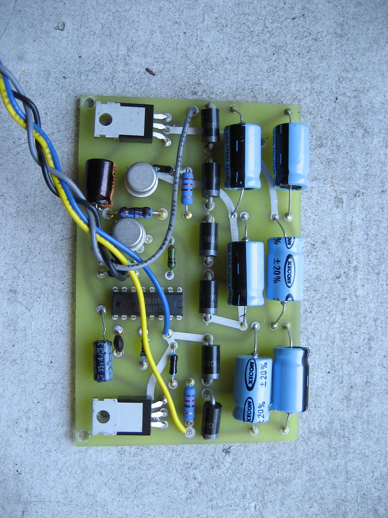
In my post about the Music Easel, I mentioned my clone of the 214 power booster board. Here's a picture of it.


Here is the original.


And, here is the reverse engineered schematic I made.


Since I traced this, I have seen another one that had most of the values changed, but you get the idea. Here it is inside Reed's 300 cabinet. Notice the red velvet trim on this bad boy.

The 266 project

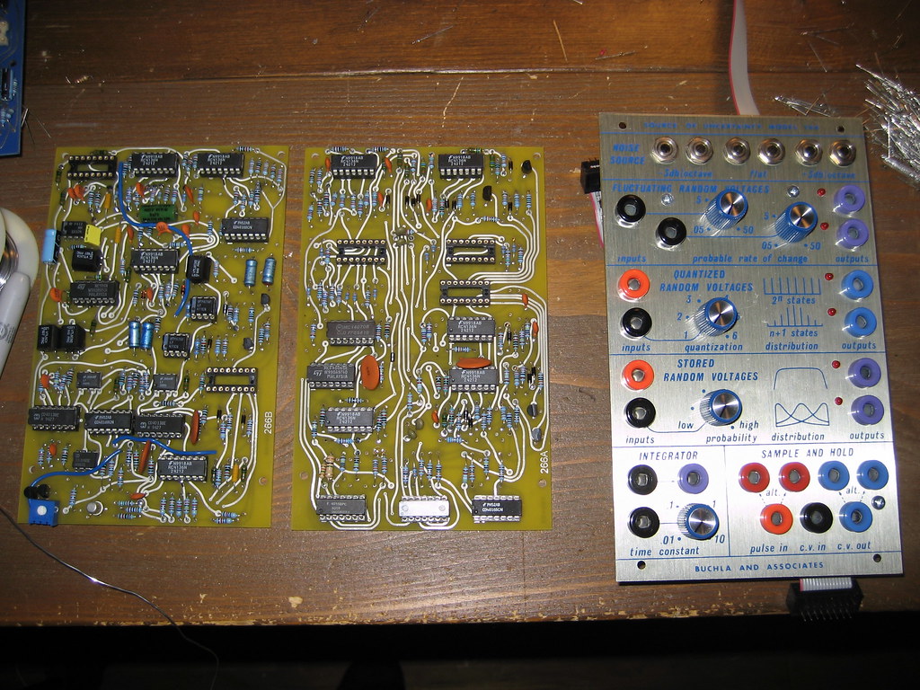
The Audities Foundation got whatever parts were left in Don's archives during the garage sale about 6 years ago. Included in that lot were 2 unused 266 Source Of Uncertainty panels. I built this one and am working on the other.

Obviously, this is a very popular module and every Buchla user wants to have one, but without any circuit boards nobody was jumping at it. A couple "kits" for this module went out the door at the same time. So I was fortunate to track down some scans of the circuit boards without any parts installed. Then came the long process of cloning them. This module has 3 PCBs inside. The motherboard (with all the panel components on it), A and B.


I know, I know. "They're not blue!" Well, I didn't feel that it was necessary to make the PCBs the same color as the originals. The second cry is, "But there are no orange banana jacks on MY 266!" True, the original release of the 266 used red banana jacks for both pulse input and pulse output jacks, but since Don changed to orange for pulse inputs in the late 70s and is still using that standard today I went with the new standard. It turned out that I made several errors in my cloning of the PCBs, leaving short traces between pins on ICs off. It's ended up working after a little stress and now lives happily between a 265 and a 266e. Long live the Source of Uncertainty.

Why Buchla?

Since this is the first post, I'd like to start by explaining why I vote Buchla.

The Buchla 200 is the best modular electronic instrument ever made.

1. Don Buchla designed the front panel of his instruments first and the electronics second. A musician himself, this means that each module was an idea for a musician's tool rather than an engineer's.

2. Audio paths and control paths are totally divided. The control path uses unshielded stacking banana cables. The audio path uses 1/8" mini cables. On early modules the control paths and signal paths even used separate power rails! The audio signals are line level, just like all the signals in a recording studio, so patching in and out of the system is seamless. The stacking bananas are great for control signals, they mult simply. The EF Johnson banana jacks come in a variety of colors, which Don used to code what the jacks are used for.

3. Controls sweep within a musically useful range. This is in some ways related to #2. Because audio processing modules never have to concern themselves with CV signals and vice versa, the controls don't have half of their rotation representing useless values, like a Serge.

4. "Unencumbered by engineering expediency or presumed musical asthetics..." Taken from the 248 catalog page.

5. Circuit boards are all mounted parallel to the panel, making the system take up less space behind the panel than most modulars. This allows for the suitcase cabinets and folding 203 cabinets. I will never understand the MOTM/Moog/Blacet/whatever system of mounting PCBs sticking way out back.

6. Sound design emphesis taken away from "fat" and "juicy" 24dB/Oct. lopass type sounds and into more interesting textures. Sure, you can do FM, AM, whatever audio rate modulation on any modular, but Buchla really pushes the user that way. The 259 has a switch and VCA internally patched for FM. It has a dedicated modulation oscillator!

7. Analog address of sequencers. Most of the time a sequencer is simply going to be pulsed along linearly. But having the CV in to sweep through the range of steps allows the sequencer to be used in several new ways including as a quantizer, tracking generator and more.

8. Harmonic Generator. No other modular ever had an oscillator module with the first 10 harmonic sine waves available. Don updated his 148 module for the 200 series too, but only made 2 as far as I know.

9. Source of Uncertainty. These days, all modulars have noise and sample & hold modules, but nobody ever made so many specific and musical options available to make sounds randomly shift and evolve. All hail the 266!

10. Quadrature mode on the 281. After a while, the ADSR became de facto for the whole of the synth industry. The 281 module allows all of the modes on a 284 or a 280 to be achieved, with voltage control of each stage. It's the quad mode that allows a quadrature LFO to be created, for quad panning or whatever. However, this mode can also be used to creat ADSR and DASR envelopes. I like the ADSR that you get from this because it follows through the whole decay and release cycles, even when it only gets a short pulse.

11. "Timbre." No, I don't mean the sound of the machine, at least not in this case. I mean the "timbre" circuit that is inside the 208 and the 259. It involves wave folding similar to the Serge wave multiplier (totally different circuit) attached to the sine wave output from the oscillator. The 258 already had the ability to sweep from a sine wave to either a saw or square wave, which is a bit like lopass filtering. A sweep of the "timbre" sounds unlike any other synth and is amazing.

12. Voltage Controlled Panning. The 207 allows 2 channels to be sweeped around via a CV. The 227 and 204 allow quad panning from 2 CVs. Simple yet wonderful.

13. Tunable Touchplate Keyboards. Those users who have no interest in playing a piano keyboard can rig up a 217 to do lots of things that no other system has ever allowed.

14. VTL5C3. The vactrol used in the 292 lopass gate has a characteristic slew to it. It makes the attack of any note from a Buchla 200 a little round. The "woodiness" of the sound is a key reason that the Buchla's sound has been discribed as natural.


I'm sure there are more reasons that will come to me as soon as I post this, but it will do for now.